 I now have the door panels assembled and roughly fitted to the cabinet front enclosure. In the previous post I mentioned that I had stumbled on to some nicely figured European beech. This is an excellent example of the concept and term dynamic design I described in a much earlier post. As much as I like to follow through with a pre-existing design, when an opportunity presents itself and I can enhance a design,a strong consideration is given to seizing this opportunity. My original design was nebulous regarding the front doors, I had some sort of inlay in mind as an embellishment. The figure I have found in these slices of European beech are, in my opinion, a more natural embellishment and if oriented correctly, dramatically change the front graphics of the cabinet. Some judicious resawing and a short time later and I had enough veneer slices to create the bookmatched veneers for the fronts of the door panels. I utilize straight-grained beech veneers for the back of the door panels. The veneers are edge jointed prior to assembling together to form each of the four sheets for the two door panels. I take great care in veneering the substrates for the door panels and make sure that the substrates are perfectly flat and smooth since the veneers will telegraph any bumps or surface irregularities into the top surface.
In the photo, I have the door panels mocked up in the cabinet front to determine if the aesthetics are both correct and pleasing. I'm not looking for complete symmetry at this point and this is obvious in the detail of the figure of the individual door panels. There is instead, a partial symmetry in the door graphics which makes us more aware of the natural growth pattern of wood.
Next I make preparations for installation of the knife hinges for the doors after some final fitting of the doors within the cabinet opening.
 I have begun work on the front doors in the past day or so. I'm not sure if you recall, but in an earlier post I decided to create the doors of the cabinet as veneered panels rather than solid wood. The primary reason for this is the width of each of the doors and the large expansion and contraction coefficient of the solid wood, along with the exceptional stability of veneered panels. Although I had originally intended to use quarter-sawn wood, the expansion rate is still uncomfortably large with the approximate 13 inches of width for each door. The first part of creating the individual doors is to have a straight, flat and solid substrate. I have selected multi-ply baltic birch for the substrate, the virtues of this wood are dimensional stability and strength. It is very well suited for use as a substrate for veneering.After cutting the pieces for each door to approximate size, I added some solid beech edging to all four sides of each panel. This allows me to overlap the veneer the full expanse of each panel and in turn I gain solid wood at each of the ends and sides. As part of the design I need to have solid wood at the junction of the doors to be able to create a rabbeted lip. The strips of beech I use along with the substrate together provide me with two oversized door panels which I will trim after veneering.
While the glue is setting on the substrate door panels, I take the opportunity to lay out some veneer pieces from solid European Beech stock I have. Once the stock is marked I begin to resaw the veneers. This operation is fairly slow as each piece of veneer needs to be sawn fairly uniform in thickness and with minimal saw marks and due to the depth or width of the veneers, the stock can only be passed through the bandsaw at a low feed speed. While laying out the veneers I stumbled across some nicely figured stock which I will use to create the veneers for the front of the doors. This was not anticipated and a welcome surprise, the inherent beauty of wood and the surprises it holds. I now need to spend a little more time bookmatching the figured veneer for each door panel. Hopefully this will work out and the veneered sheets come out fine.
Next I will continue to work on the veneers and use the individual veneer slices to create sheets large enough to cover each side of the door panels. Working with thin sheets of veneer like this involves careful attention to their fragile nature. Although the resawn veneers I am creating are an order of magnitude thicker than commercial veneers, they can still be fragile.
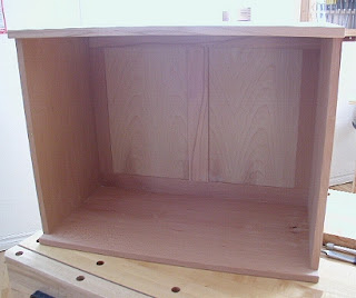 The back frame and panel is assembled with panels in place and installed at the back of the cabinet. The cabinet is slowly evolving into a piece of furniture. The frame and panel back fit very snugly after some light, judicious planing of the outside rails and stiles. I have not yet finalized the layout of the interior of the cabinet, but I expect to create an assembly with two or three drawers in the lower right section of the cabinet. In the photo, you can see the overhang at the front top and bottom of the cabinet to allow for the front doors. The amount of overhang or space I allowed for is the thickness of the individual veneered door panels along with a very small extra gap both behind and ahead of the door.There is also the small chamfered edge of the top and bottom surrounding the cabinet front, sides and back. Creating the door panels is my next task in this cabinet build and I will be working on this over the next days. I'm also working on the stand design which has not yet been finalized. I have a feeling I will be modifying the original drawings and doing something a little different here. I'm just waiting to determine how the enclosed cabinet looks to me and what stand design provides the best complement for the cabinet. This goes back to a term I coined a few months ago on an earlier project.
The term I coined is "dynamic design" and allows the maker to dynamically modify a design as the build progresses. The modifications in design are directly attributable to how the project is taking shape, as opposed to moving forward with an existing design which might or might not make sense any longer. The concept of dynamic design and artistic freedom go hand in hand. I mention to my clients that the design will most likely evolve as the project continues and to expect some changes, most likely small ones. There needs to be a certain trust between the maker and client to be able to accomplish this, something I strive to provide the client.
I should have the beginnings of the door panels done in the next day or so along with resawing of the veneers I will be using.
 I've been working on the frame and panel for the back of the cabinet. This frame is composed of the same wood, European beech, as the cabinet. The components of the frame and panel back are two outside stiles, a center stile, and the upper and lower rails which are continuous along their length. The width of the individual components is approximately 2 inches or thereabouts, and I based this on aesthetics along with availability of clear quarter-sawn beech stock on hand. The type of joinery I have selected for this back is the mortise and tenon. The stiles are of equal length, so are the the respective tenons at either end of each stile, which also fit into the grooves in either horizontal rail. In the photo, the frame is temporarily installed in the cabinet back recess for a test fit. I am in the process of creating the panels to fit into each of the frame halves.Some judicious planing is involved in creating a perfect fit of the frame and panel into the back of the cabinet, but I had already allowed for this with a very small fraction of an inch in extra width of the frame. Another factor in the decision for the stile and rail widths is the factoring in of any small wood movement of the rails and stiles in their widths. The wood I have selected is fairly quarter-sawn so movement is substantially reduced and the fairly narrow widths of the components reduces the remaining movement considerably. The panels will be floating with a small gap around each edge to allow for wood movement. Once I have this frame and panel back installed, the cabinet will have developed an entirely new look, that of a cabinet without front doors.
 I use dowels to join the panels together, the sides together, the sides to the top and bottom. The main reason for this type of joinery in this particular application is that it allows me to have a slight overhang of the top and bottom panels vis a vis the sides, to accommodate the chamfered edges.. Alternative methods of joinery that allow this are mortise and tenon, sliding dovetails. etc. I use dowels as I feel comfortable with this joinery and it has not let me down so far. A considerable amount of accuracy is necessary in aligning the dowel holes that mate with the top, bottom and side panels. There are also different methods to accomplish this. The simplest method is to use dowel centers, next would be a doweling jig of some sort.Instead, I make a doweling guide which is simply a block of wood with the exact dimensions , thickness and length of each of the side panels. The concept is to use the guide to create mating dowel holes in the ends of the panels. I use standard size fluted dowels and have pre-measured and carefully oriented each of the side panels to its corresponding top and bottom panel. In the photo, I am aligning the doweling guide on one of the side panels. I since removed and bored two other holes in this particular guide for a total of ten dowel holes. Also in the photo, the face of the side panel is displayed, the back of this panel has a rabbet running lengthwise at the left hand side. The first dowel hole from the left is offset to accommodate this.
As I continue with this boring process ( no pun intended) there are eventually a total of 80 holes bored into the ends of each of the panels. A stop is used to bore to the correct depth to accommodate standard size dowels. Afterwards, each of the bored holes is checked with the depth gauge of a caliper and install the dowels, first on the side panels, then these panels to the top and bottom panels. Some test fitting, and the glue up begins...
 My next logical step in the progression is to create the rabbets for the frame and panel back. The rabbets in the left and right side panels are fairly straightforward. I selected a 5/8 inch depth and 5/16 inch width for the rabbet. The 5/8 inch thick frame provides sufficient strength for the 5/16 inch back panels. The will be two back panels housed in the frame which is divided by a center stile, or at least this is what the plan is. It is fairly important to have the depth of the rabbet uniform in both side panels and the top and bottom panels, this involves careful measuring and allowance for the chamfer edge profile of the top and bottom panels.
The rabbet in the top and bottom panels is a stopped rabbet, ending just before either end of the back of each of the top and bottom panels. After removing most of the wood to create the rabbet, I squared the ends of the rabbet using chisels and careful marking. To ensure all the panels are squared up and exactly the same size I overlay the top panel onto bottom panel without the side panels and then with the side panels in place.
In the photo, the panels are loosely assembled to confirm all the rabbets are the same depth and uniform around the carcase. I also take this opportunity to mark the outline of each of the side panels onto the top and bottom panels. This paves the way for the next step which is to create the joinery for the panels, in this case dowels. I create a doweling guide which is the same dimension, thickness and width as one of the ends of the side panels.
More about this in the next post..
 I left off preparing the four panels which comprise the carcase of the cabinet. Since then, I've spent more time on the four panels and in particular the top and bottom panels. After some final smoothing and scraping of the faces I began preparing the edges. I hand plane the edges at the ends of each of these panels with a block plane set to a light cut. This leaves a nice, smooth edge at the ends as opposed to a slightly fuzzy edge before hand planing. Once I have this edge planing complete, the top and bottom panels are checked to confirm that they are the exact width and length and perfectly square to each other. The profile I have decided on for the edges of the top and bottom panels is an approx. 3/32 inch wide 45 degree chamfer which I accomplish with a block plane as shown in the photo. Beginning with the edges at the end and finishing with the long edges, I create these very small chamfers. Some judicious, careful hand planing is necessary here to maintain the correct chamfer width along the length of the end and long edges of each panel, both top and bottom. It's actually easier than I describe once a rhythm is established. I find the 45 degree angle is easy to visualize and set as opposed to any other angle between 0 and 90 degrees. The profiled edges are important to create at this stage since the next steps involve attaching the side panels to the top and bottom panels. It will be virtually impossible to create the profiles afterwards.
Next, I will complete preparing the side panels, confirm they are square to each other and identical in length and width and begin to mark their orientation to the top and bottom panels. The side panels will be set back approx. 3/4 inch from the front edge of the cabinet to allow for the doors. The doors are veneered panels with a finished thickness of just under 3/4 inches. The side panels are to be attached to the top and bottom panels with a series of dowels and the creation of the doweling template jig specific to this cabinet is also next in the sequence of steps to be performed.
Another of the next steps is to create a rabbet for the back panel. This back panel, a frame and panel and yet to be created, will be housed into both the top, bottom, and side panels.
 I left off with four carcase panels which needed to be dimensioned and flattened to exact and uniform thickness. At this point, the panels are roughly at the final thickness and ready to be hand planed for a smooth, uniform finish across the complete panel in both width and length. I use an accurate solid steel straightedge to determine the high spots on the panels, this after a final check with winding sticks to check for any small, remaining twist. The process I use is to slide the steel straightedge across the width of each panel along its length and marking with a pencil any dips or bumps or any cupping. Since each of these panels is approximately 14 inches wide, there is bound to be some irregularity on the surfaces until I hand plane these surfaces. Each side of each panels is flattened similarly with the final thickness of each board constantly in mind. The final thickness, in this case 11/16 inch, needs to be accurately maintained throughout the panels, both across the panel and along the length of the panel. I have made a few passes with a long jointer plane with a long bearing surface to make quick work of any bumps and hollows over the length of the panels. Afterwards, I switch to a smoother plane and smooth the panels further until the high and low spots disappear, all the while I reducing the depth of iron in my smoother plane to take progressively lighter shavings. I'm also using my widest smoother, No. 4.5, for this application, this provides less overlap in the plane strokes and covers more area quickly. A stick of wax is your friend when doing this type of work, this keeps the hand plane gliding smoothly and somewhat effortlessly. When I assembled the panels from boards earlier I made sure to orient the grain of the boards in the same direction, this decision is now obvious as a wise decision since hand planing can be accomplished in the correct direction.
Once I have a rhythm established, flattening these panels is actually an enjoyable task. Tearout is non-existent since I'm planing with the grain and the beech panels are fairly tame, so all I get is nice, fluffy shavings. I had to watch myself to not get carried away. At this time, I have four panels hand planed to thickness (uniform thickness) and perfectly smooth , as determined from some final checking with the solid steel straightedge.
Next I will dimension each of the two side panels and the top and bottom panels to the final width and length which the design calls for.
 Sometimes I spend time researching past furniture styles. I often read that much today has already been done before, and after seeing some good examples of period furniture, find some truth in this old adage. My favorite influential maker is George Hepplewhite and the associated furniture of his era. Furniture of the late 18th century has been mostly characterized by Chippendale and the cabriole leg design element. George Hepplewhite, however, is much less written about and known, and was characterized by the slight, tapered legs of his furniture and lightness and delicacy of his pieces. A considerable amount of 20th century furniture has been derived from this late 18th , early 19th century period and in particular the makers Chippendale and Hepplewhite. American Federal style furniture had its origins in the Hepplewhite style. Much of the design elements of this particular period have made their way into furniture of the past century. This can be considered a "revival" of a previous style in time, but I like to think of it as simply embracing design elements which were and continue to be pleasing to the eye..When I flip through examples of furniture representative of previous periods and styles, it is easy to see what worked and what didn't work. The design elements which are pleasing and well-proportioned are carried into later periods, whereas the not so pleasing styles typically die off. Another trend which I notice is how previous styles of furniture are sometimes renounced and discarded only to be replaced with a radically different style of furniture. We see this very same phenomenon today in everything ranging from fashion, automobiles, and continue to see it in furniture styles. A "revival" of a previous period or style of furniture then occurs, much like what occurs in the fashion world today.
The reason I raise this is that this is something to consider for furniture makers today. We all have our favorite style as makers, but it may be important to incorporate proven design elements in our designs, the elements which have demonstrated the most success over the past few centuries. Since what we are designing is often derived from a previous style or work, it makes more sense to derive elements from the successful styles of furniture.
I'm a big fan of clean, simple lines with minimal adornment, although I like to incorporate some inlay into my work. The inlay work sparks my creativity and in a strange way provides me the impetus to complete the furniture so as to add the inlay detail. I can relate the piece of furniture to a large canvas and the inlay is the artwork. Other makers might define themselves through another feature on their work, perhaps some carving or marquetry. George Hepplewhite often distinguished his work with added inlay. A large proportion of Hepplewhite and Federal style furniture is inlaid with the exotic woods which had come into popularity by the late part of the 18th century and early 19th century.
More on this later...
 I resume work on the cabinet on stand this week
.
In the meantime, I have assembled the panels from the boards I had partially completed in the last post. This process consists of having one face of the boards flat along with one edge. Careful planning along with board layout is involved. The grain orientation of the two boards which comprise each of the panels should run in the same direction. I have marked the individual boards and edges correspondingly and then prepare the edges of the boards which mate together. I accomplish this by hand using a jointer plane along with regularly checking that the edge of each board is perfectly square to the flat face of the board. The edges of the individual boards need to mate perfectly in two planes, across the edge and along the edge.
Once I've accomplished this, I introduce a slight hollow in each long edge just shy of the ends of the boards. The hollow is precisely one very thin shaving thick. This creates a very small spring in the joint which is closed when the boards are clamped together. The spring also serves another purpose, to make certain that the ends do not open up in the future due to wood shrinkage. Introducing spring or hollow in the edge joint can be controversial sometimes, with different opinions shared by different people. I simply do what works for me. After having oriented, assembled, and glued each of the four panels together, my next step was to begin to size the dimensions of each of the panels. At this point the panels are each slightly oversize in both length and width and ready for final preparation. The final preparation stage consists of hand planing each of the two surfaces of each panel with a smoother plane working towards four perfectly flat panels. The value of the earlier step of having the grain orientation of each of the two boards in each panel running in the same direction is greatly appreciated now. Because of this previous consideration, there should be no issues with tearout with hand planing. Afterwards, I will trim the panels to the final dimension.Not sure about the rest of you, but we're experiencing one of the largest snowfalls in the past years in this part of the country. It seems to snow every other day, and folks are complaining that they've run out of space to put it all. I kind of don't mind as it extends the ski season well into spring, which is my favourite time to get out and do downhill skiing.
 I left off in my last post with a few boards in the process of acclimatizing to my work area and to relieve any built up stress in the wood. A few days have elapsed and as expected, there is a little tendency of cupping and bowing in some of the individual boards. This is minimal, but nonetheless needs to be addressed. One face of each of the boards needs to be perfectly flat in both width and length. I continued to process each of the boards today to make certain this one face also known as the reference face of the boards, is true and flat. The thickness of the individual boards is slightly greater than I need for a final thickness and this will allow me to plane the opposite face to the exact final thickness I need. In the photo I have a few of the boards after some more preparation along with some of the tools I use to measure any cup or bow in each board. At the left, there is also a solid steel straight edge which I use to check bow along the length of the board. The combination square at right serves to any cupping of the boards along their width. The small steel engineers square is used to measure the long edge of the board to confirm it is square to the reference face.These past few days have also allowed me to temporarily switch my focus to another endeavor. My wife has slowly been ramping her small business up, and over a week ago we decided to take some concrete steps to get it established. The business is now set up, and I have also set up her web site. This past Saturday, Linda had her very first showing at the grand opening of a small tea house and shop in our area. This is a very heady and exciting period for her, it sort of reminds me of myself when I began my original business a few years ago. I'll post her web site if anyone is interested in having a look: http://www.fusionjewelrydesign.com/

 I now have the door panels assembled and roughly fitted to the cabinet front enclosure. In the previous post I mentioned that I had stumbled on to some nicely figured European beech. This is an excellent example of the concept and term dynamic design I described in a much earlier post. As much as I like to follow through with a pre-existing design, when an opportunity presents itself and I can enhance a design,a strong consideration is given to seizing this opportunity. My original design was nebulous regarding the front doors, I had some sort of inlay in mind as an embellishment. The figure I have found in these slices of European beech are, in my opinion, a more natural embellishment and if oriented correctly, dramatically change the front graphics of the cabinet.


